


What Is an Optimized Linear Motion System?
An optimized linear motion system converts rotary or electromagnetic drive force into precise straight-line travel. It holds position error, vibration, and settling time to the lowest practical level. In industrial automation, engineers achieve this by matching guide rail geometry, drive type, and servo control tuning to the actual load, speed, and duty cycle of the application. Therefore, engineers treat optimized linear motion as a system-level discipline, not a single component upgrade. A profiled rail alone cannot deliver optimized motion. The rail, carriage, drive mechanism, and controller must work as one tuned assembly. Every design review should evaluate stiffness, thermal behavior, and feedback resolution together. Otherwise, a strong rail paired with a poorly tuned servo loop still produces overshoot and settling delay. This combined view explains why "optimized linear motion" describes an engineering outcome, not a fixed product category.
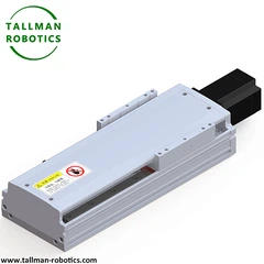
Here we introduce our TMS seires Linear Motion System to you.
|
Model No |
Max Payload(kgs) |
Max Stroke(mm) |
Repeatability(mm) |
Drive Solution |
Motor Power (W) |
|
TMS30 |
4 |
400 |
±0.01/±0.005 |
screw |
30 |
|
TMS45 |
10 |
800 |
±0.01/±0.005 |
screw |
50/100 |
|
TMB45 |
4 |
800 |
±0.04 |
belt |
50/100 |
|
TMS62 |
20 |
1050 |
±0.01/±0.005 |
screw |
100/200/400 |
|
TMB62 |
16 |
2000 |
±0.04 |
belt |
100/200/400 |
|
TMS65 |
30 |
800 |
±0.01/±0.005 |
screw |
50/100 |
|
TMB65 |
4 |
800 |
±0.04 |
belt |
50/100 |
|
TMS85 |
50 |
1050 |
±0.01/±0.005 |
screw |
100/200/400 |
|
TMB85 |
16 |
2000 |
±0.04 |
belt |
100/200/400 |
|
TMS100 |
65 |
1050 |
±0.01/±0.005 |
screw |
100/200/400 |
|
TMB100 |
40 |
3500 |
±0.04 |
belt |
100/200/400 |
|
TMS135 |
110 |
1250 |
±0.01/±0.005 |
screw |
200/400/750 |
|
TMB135 |
42 |
3500 |
±0.04 |
belt |
200/400 |
|
TMS150 |
120 |
1500 |
±0.01/±0.005 |
screw |
400/750 |
|
TMB150 |
75 |
3500 |
±0.04 |
belt |
400/750 |
|
TMS170 |
130 |
1500 |
±0.01/±0.005 |
screw |
400/750 |
|
TMB170 |
75 |
3500 |
±0.04 |
belt |
400/750 |
|
TMS220 |
150 |
1500 |
±0.01/±0.005 |
screw |
750 |
|
TMB220 |
75 |
3500 |
±0.04 |
belt |
750 |
You are welcome to watch more projects or visit our video gallery by Youtube: https://www.youtube.com/@tallmanrobotics


Structural Components That Enable Optimized Performance
A linear motion system reaches its optimized state through five coordinated elements. First, the profiled linear guide rail carries radial and moment loads. It also keeps runout within a few microns across the travel length. Second, the recirculating carriage rides the rail on preloaded ball or roller elements. Correct preload removes clearance without adding excess friction. Third, the drive mechanism converts servo motor torque into linear thrust. A ball screw drive suits high-load axial precision. A belt-driven linear module suits long-travel, high-speed axes instead.
Fourth, the servo motor control loop applies current, velocity, and position gains. Engineers tune these gains to the mounted mass and travel length. Fifth, linear encoder feedback closes the loop with direct position measurement. This feedback bypasses the small errors that screw pitch or belt stretch would otherwise introduce.
|
Component |
Primary Function |
Typical Optimization Target |
|
Profiled guide rail |
Carries load, defines travel path |
Straightness within a few microns per meter |
|
Recirculating carriage |
Transfers load to rail with rolling contact |
Preload tuned to load direction and magnitude |
|
Ball screw drive |
High-precision axial thrust |
Backlash near zero, lead accuracy per ISO 3408 |
|
Belt-driven linear module |
Long-travel, high-speed thrust |
Belt tension matched to acceleration profile |
|
Servo motor control |
Converts electrical signal to motion |
Gain tuning matched to mounted inertia |
|
Linear encoder feedback |
Direct position measurement |
Resolution matched to required positioning accuracy |
Motion Profile and Servo Control Optimization
Positioning accuracy depends heavily on the motion profile the controller commands. Mechanical build quality alone does not guarantee it. An S-curve motion profile limits jerk during acceleration and deceleration. As a result, the carriage reaches speed smoothly and settles faster at the target point. A trapezoidal profile suits simpler point-to-point tasks instead, where jerk control matters less. Engineers select the profile shape first. Then they tune servo motor control gains around that shape. Otherwise, gain values that work for a trapezoidal move often cause overshoot under an S-curve command. Linear encoder feedback then verifies whether the tuned system meets its positioning accuracy target under real load. A no-load bench test cannot confirm this on its own.
Resonance sometimes appears near the mechanical natural frequency of the carriage and payload. In this case, engineers apply a notch filter in the drive rather than lowering gains across the whole loop. Indeed, a global gain reduction still sacrifices settling time everywhere on the axis.
Application Areas for Optimized Linear Motion
Optimized linear motion supports several demanding verticals across industrial automation. In semiconductor handling, wafer transport stages depend on sub-micron positioning accuracy and minimal vibration during high-speed indexing. In food and beverage packaging, washdown-rated modules require optimized sealing alongside standard motion tuning. Here, contamination control cannot compromise cycle time. In medical device assembly, repeatable short-stroke motion supports tasks such as component insertion and inspection alignment. In automotive and new energy manufacturing, longer-travel gantry axes move heavier payloads across battery, motor, and body assembly stations. In general packaging lines, belt-driven linear modules favor speed and travel length over extreme stiffness. Ball screw drives provide that stiffness for other tasks instead. Overall, the optimization approach stays consistent across all five verticals. Engineers match rail size and drive type to load first, then tune the servo loop to the resulting motion profile.
Performance Gains: A Quantified Case Reference
Independent engineering sources confirm what system-level optimization can achieve. A dual-gantry linear stage architecture, built for semiconductor metrology, reached accelerations up to 5 g. It also held positioning accuracy at 0.5 micron. Engineers attributed this result to uncoupling the X and Y axes and using a lightweight, high-stiffness cross-member (SCHNEEBERGER, 2023). Separately, tighter CNC thread-rolling control now improves leadscrew manufacturing. As a result, leadscrews hold positioning repeatability within 1 micron over a single rotation. This performance level directly benefits wafer handling and syringe-pump dispensing equipment (Linear Motion Tips, 2019). These figures illustrate why optimization efforts increasingly focus on the drive mechanism and structural stiffness together. Engineers no longer treat them as separate design steps.
Frequently Asked Questions
1. What distinguishes an optimized linear motion system from a standard linear module?
A standard module meets baseline travel and load specifications. An optimized system additionally matches motion profile, servo gain tuning, and feedback resolution to the specific application. As a result, positioning accuracy and settling time meet the target under real operating conditions, not only under bench testing.
2. Should I choose a ball screw drive or a belt-driven linear module for an optimized axis?
Choose a ball screw drive for high stiffness and fine positioning accuracy over shorter travel. Choose a belt-driven linear module instead for longer travel and higher speed. This second option fits best when the load does not demand screw-level rigidity.
3. How does linear encoder feedback improve optimization compared to motor-only feedback?
Linear encoder feedback measures carriage position directly. Therefore, it captures errors from screw pitch variation, belt stretch, and thermal expansion that motor-only feedback cannot see. This direct measurement lets the servo loop correct for real mechanical behavior, not an assumed ideal.
4. What causes resonance in an optimized linear motion axis, and how is it resolved?
Resonance typically appears near the natural frequency of the carriage and mounted payload. This happens once servo gains push response speed higher. Engineers then address it with a notch filter tuned to that frequency. This approach preserves loop gain everywhere else on the axis.
5. How often should an optimized linear motion system be re-verified after installation?
Re-verify positioning accuracy and encoder alignment following any mechanical service, coupling replacement, or payload change. These events can shift the tuning baseline established during commissioning. A scheduled annual check is also reasonable for continuous-duty production axes.
Hot Tags: optimized linear motion, China optimized linear motion manufacturers, suppliers, factory, Precision Positioning, Cross Roller Stage, Linear Feed Platform, Miniature Linear Actuator, Ball Screw Driven Linear Stage, Linear Material Transfer Unit


