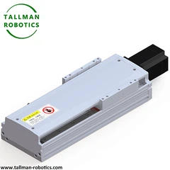


Screw Linear Module is a mechanical device designed to provide precise linear motion in automation and industrial systems. It uses a screw mechanism-typically a ball screw or lead screw-to convert rotational motion into straight-line movement. These modules are widely used where accuracy, repeatability, and controlled motion are required.
Screw Linear Modules are essential mechanical devices used to control linear motion in an accurate and efficient way. They consist of a lead screw, a motor, a guide rail, and a housing unit. At the core of their design is the lead screw, which converts rotational motion from the motor into precise linear movement. The guide rail works to ensure that the moving components travel smoothly and without unnecessary deviation. The housing provides support and protection, making the module durable and reliable for long-term use.
The basic structure of a Screw Linear Module includes a screw shaft (ball screw or lead screw), a motor (servo, stepper, or AC/DC), a nut assembly, and a linear guide system. The motor rotates the screw, causing the nut to move along its length, pushing or pulling the attached load. Many modules also incorporate sensors and controllers to enhance positioning accuracy. Their compact and rigid design makes them suitable for high-load applications while maintaining smooth operation.
Working principle of Screw Linear Module: Spiral transmission principle based on screw nut - When the motor drives the screw to rotate, the nut cannot rotate synchronously with the screw due to thread constraints and can only move in a straight line along the screw axis; The guiding system restricts the radial movement and rotation of the nut, ensuring that it moves strictly along a linear trajectory. Ball screws reduce friction through ball bearings, achieving a transmission efficiency of 85% -95%; Trapezoidal screw is a sliding friction with low efficiency (20% -40%), but it has low cost and self-locking properties (the load does not move after power failure).
You are welcome to watch more projects or visit our video gallery by Youtube: https://www.youtube.com/@tallmanrobotics
Ball Screw Linear Modules for General Environment from Tallman Robot have following series TMS-CM:
|
Model No |
Body Width (mm) |
Max Payload (kgs) |
Max Stroke (mm) |
Repeatability (mm) |
Drive |
Motor Power (W) |
Application Environment |
|
TM-S45-CM |
45 |
10 |
800 |
±0.01/±0.005 |
screw |
50/100 |
General |
|
TM-S62-CM |
62 |
20 |
1050 |
±0.01/±0.005 |
screw |
100/200/400 |
General |
|
TM-S65-CM |
65 |
30 |
800 |
±0.01/±0.005 |
screw |
50/100 |
General |
|
TM-S85-CM |
85 |
50 |
1050 |
±0.01/±0.005 |
screw |
100/200/400 |
General |
|
TM-S100-CM |
100 |
65 |
1050 |
±0.01/±0.005 |
screw |
100/200/400 |
General |
|
TM-S100L-CM |
100 |
80 |
1050 |
±0.01/±0.005 |
screw |
100/200/400 |
General |
|
TM-S135-CM |
135 |
110 |
1250 |
±0.01/±0.005 |
screw |
200/400/750 |
General |
|
TM-S150-CM |
150 |
120 |
1500 |
±0.01/±0.005 |
screw |
400/750 |
General |
|
TM-S170-CM |
170 |
130 |
1500 |
±0.01/±0.005 |
screw |
400/750 |
General |
|
TM-S220-CM |
220 |
150 |
1500 |
±0.01/±0.005 |
screw |
750 |
General |
Ball Screw Linear Module for Dust-proof Environment from Tallman Robot have following series TMS-CR
|
Model No |
Body Width (mm) |
Max Payload (kgs) |
Max Stroke (mm) |
Repeatability (mm) |
Drive |
Motor Power (W) |
Application Environment |
|
TM-S45-CM |
45 |
10 |
800 |
±0.01/±0.005 |
screw |
50/100 |
General |
|
TM-S62-CM |
62 |
20 |
1050 |
±0.01/±0.005 |
screw |
100/200/400 |
General |
|
TM-S65-CM |
65 |
30 |
800 |
±0.01/±0.005 |
screw |
50/100 |
General |
|
TM-S85-CM |
85 |
50 |
1050 |
±0.01/±0.005 |
screw |
100/200/400 |
General |
|
TM-S100-CM |
100 |
65 |
1050 |
±0.01/±0.005 |
screw |
100/200/400 |
General |
|
TM-S100L-CM |
100 |
80 |
1050 |
±0.01/±0.005 |
screw |
100/200/400 |
General |
|
TM-S135-CM |
135 |
110 |
1250 |
±0.01/±0.005 |
screw |
200/400/750 |
General |
|
TM-S150-CM |
150 |
120 |
1500 |
±0.01/±0.005 |
screw |
400/750 |
General |
|
TM-S170-CM |
170 |
130 |
1500 |
±0.01/±0.005 |
screw |
400/750 |
General |
|
TM-S220-CM |
220 |
150 |
1500 |
±0.01/±0.005 |
screw |
750 |
General |
Long Stroke Screw Linear Module for General Environment TM-SL-CM
|
Model No |
Body Width (mm) |
Max Payload (kgs) |
Max Stroke (mm) |
Repeatability (mm) |
Drive |
Motor Power (W) |
Application Environment |
|
TM-SL135-CM |
135 |
80 |
2200 |
±0.01/±0.005 |
screw |
200/400/750 |
General |
|
TM-SL170-CM |
170 |
110 |
2200 |
±0.01/±0.005 |
screw |
400/750 |
General |
|
TM-SL220-CM |
220 |
150 |
2400 |
±0.01/±0.005 |
screw |
750 |
General |
Organ Cover Water proof Lead Screw Linear Modules TM-SF
|
Model No |
Body Width (mm) |
Max Payload (kgs) |
Max Stroke (mm) |
Repeatability (mm) |
Drive |
Motor Power (W) |
Application Environment |
|
|
TM-SF100-CR |
140 |
65 |
1050 |
±0.01/±0.005 |
Screw |
100/200/400 |
Water-proof/Dust-proof |
|
|
TM-SF135-CR |
171 |
80 |
1250 |
±0.01/±0.005 |
Screw |
200/400/750 |
Water-proof/Dust-proof |
|
|
TM-SF170-CR |
206 |
110 |
1500 |
±0.01/±0.005 |
Screw |
400/750 |
Water-proof/Dust-proof |
|
|
TM-SF220-CR |
256 |
150 |
1500 |
±0.01/±0.005 |
Screw |
750 |
Water-proof/Dust-proof |
|


Screw Linear Modules are essential in various industries. In manufacturing automation, they position tools, assemble parts, and handle materials with precision. The semiconductor industry relies on them for delicate wafer processing and inspection systems. Medical equipment, such as imaging devices and robotic surgery tools, also use these modules for controlled movement. Additionally, they are found in packaging machinery, CNC machines, and 3D printers, where repeatable motion is critical.
What are the precautions for the installation and debugging of ball screw linear modules?
The installation and debugging of ball screw linear module directly affect their accuracy, service life, and operational stability. It is necessary to pay special attention to mechanical positioning, force balance, and parameter calibration. Specific precautions are as follows:
1. Preparation before installation for Screw Linear Module
1). Component inspection
Check if the screw rotates smoothly (without jamming or abnormal noise), if the guide rail slider moves smoothly, and if there are any foreign objects in the ball circulation system; Confirm that the module model matches the installation dimensions, and verify whether the parameters such as screw lead and rated load meet the design requirements.
2). Base treatment for Screw Linear Module
The surface of the installation base should be flat (flatness error ≤ 0.1mm/m), clean, and if necessary, use sandpaper to remove burrs; If the base is a welded component, it needs to undergo aging treatment to eliminate internal stress and avoid deformation affecting the accuracy of the module in the later stage.
2. Key points of mechanical installation for Screw Linear Module
1). Module fixation
Use the "diagonal step-by-step tightening" method to fix the module (such as gradually tightening M6 bolts with 20% -50% -100% torque, recommended torque 8-10N · m), to prevent local stress from causing deformation of the base; The installation surface should be tightly adhered to the bottom of the module, and the gap can be checked with a feeler gauge (should be less than 0.02mm), otherwise shims need to be added for adjustment.
2). Parallelism calibration
Use a dial gauge to calibrate the parallelism between the module and the motion reference (error ≤ 0.05mm/m), ensuring that the screw axis is parallel to the guide rail and reducing additional torque; Long stroke modules (>1m) need to be measured at both ends and three points in the middle to avoid base deflection affecting overall accuracy.
3). Drive connection
When the motor and screw are connected through a coupling, the coaxiality error should be ≤ 0.1mm, and the angle deviation should be ≤ 0.5 °, which can be calibrated using a laser alignment instrument; Coupling selection should match the motor torque (usually 1.5 times the rated torque) to avoid overload and breakage.
4). Load installation
The center of gravity of the load should coincide with the axis of motion of the module, and the eccentricity should be controlled within 5mm, otherwise it will increase the radial load on the guide rail and exacerbate wear; When installing vertically, it is necessary to install anti fall devices (such as electromagnetic brakes, mechanical locks) and test whether the load is stable when the power is cut off.
3.Electrical commissioning specifications of Screw Linear Module
1). Wiring inspection
The wiring of motors, encoders, and limit switches should be consistent with the drawings, with a grounding resistance of less than 4 Ω to avoid electromagnetic interference; Separate the wiring of power lines and signal lines (with a spacing of ≥ 30cm) to prevent positioning deviation caused by signal distortion.
2). Parameter settings
Before the first power on, confirm that the motor driver parameters (such as current, subdivision, acceleration time) match the motor to avoid overcurrent burnout; During trial operation, first set the low speed (≤ 50mm/s) and small acceleration (≤ 1m/s ²), and observe whether the motion is smooth.
3). Limit calibration
Adjust the mechanical limit or photoelectric switch position to ensure that there is a 5-10mm margin at both ends of the stroke to prevent hard collisions; By setting soft limit parameters through the controller, it serves as a dual protection for mechanical limit.
4. Accuracy calibration and testing for Screw Linear Module
1). Gap compensation
Use a laser interferometer to detect the reverse clearance (usually ≤ 0.01mm), and if it exceeds the tolerance, it can be compensated by pre tightening the nut (double nut structure) or controller parameters; Test the positioning accuracy at different speeds (such as 200mm/s, 500mm/s) to ensure that the error in the entire speed range is within the allowable range.
2). Run tests
Run continuously for 30 minutes, monitor the temperature of the motor and screw (should be ≤ 60 ℃), and if it overheats, check whether the load exceeds the limit or whether the lubrication is sufficient; Observe the operating noise (should be less than 65dB), abnormal noise may be caused by coupling deviation or ball wear, and the machine needs to be stopped for troubleshooting.
5.Maintenance tips after installation of Screw Linear Module
Before the first operation, add special lubricating grease (lithium based grease NLGI grade 2) to the lead screw, and inject lubricating oil (ISO VG32) into the guide rail slider; Record installation and debugging data (such as parallelism and positioning accuracy) as a benchmark reference for later maintenance.
By strictly controlling the installation accuracy (especially parallelism and coaxiality) and step-by-step debugging, the positioning error of Screw Linear Module can be controlled within 80% of the design value, and the lifespan can be extended to more than 1.5 times.
Hot Tags: screw linear modules, China screw linear modules manufacturers, suppliers, factory, Automated Ball Screw Positioning Stage, Automated Linear System, Electro Mechanical Linear System, High dynamic Linear System, Linear Indexing Table, Telescoping Linear Actuator


