
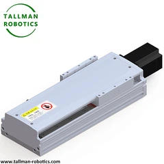


What Is a Pulley and Belt Linear System?
A Pulley and Belt Linear System uses a rotating pulley to drive a continuous belt. The belt connects mechanically with a moving carriage. As the motor turns the drive pulley, the belt travels around the pulley path. Consequently, the carriage moves along the linear guide.
A toothed timing belt provides positive engagement between the belt and pulley. Therefore, the system can maintain a controlled relationship between motor rotation and carriage travel. The pulley pitch diameter and belt pitch determine the linear travel produced by each motor revolution.
The guide system supports the carriage and controls its travel direction. Meanwhile, the belt transfers the motor force to the carriage. The tensioning mechanism maintains suitable belt engagement during operation.
This arrangement creates a complete belt driven linear actuator when engineers integrate the belt drive, guide structure, carriage, and motor interface into one mechanical assembly.
You are welcome to watch more projects or visit our video gallery by Youtube: https://www.youtube.com/@tallmanrobotics
Here, we introduce Pulley&Belt Linear System, TMB62-CM for general environment with data as follows:


Pulley and Belt Linear System Structure
A typical system contains several coordinated mechanical elements.
1. Timing Belt
The timing belt transfers rotary motion from the drive pulley to the carriage. Reinforced belt construction supports repeated acceleration and deceleration. The belt tooth profile must match the pulley tooth profile.
Therefore, engineers should select the belt according to load direction, acceleration, travel length, and operating environment.
2. Drive Pulley
The drive pulley connects with the motor shaft or gearbox output. Its teeth engage with the timing belt. As a result, motor rotation creates controlled belt movement.
The pulley pitch diameter also influences linear travel per motor revolution. Thus, pulley selection directly affects motion resolution and actuator speed.
3. Idler Pulley
The idler pulley guides the belt around the opposite end of the axis. It also maintains the belt path and supports stable belt circulation.
Depending on the mechanical layout, engineers can add additional pulleys for belt routing or multi-carriage arrangements.
4. Linear Guide and Carriage
The linear guide supports the moving load. The carriage connects the payload to the belt.
Therefore, the guide system must handle external forces and moments from the application. Engineers can select roller guides, rail guides, or shaft-based guides according to the required load arrangement.
5. Belt Tensioning Mechanism
The tensioning mechanism controls belt pretension. Correct tension helps maintain tooth engagement and reduces unwanted belt movement.
However, excessive tension can increase bearing loads and belt stress. Therefore, engineers should follow the selected belt manufacturer's tension requirements.
6. Aluminum Profile or Structural Frame
The frame supports the pulley assemblies and linear guide. An extruded aluminum profile can provide mounting surfaces for sensors, brackets, covers, and motor assemblies.
In addition, T-slots can simplify the integration of machine components.
7. Motor and Gearbox Interface
A belt driven linear module can work with a servo motor or stepper motor. A gearbox can also connect between the motor and drive pulley.
The motor provides torque, while the pulley converts rotational movement into belt travel. Consequently, the control system can command the carriage position through motor rotation.
Pulley and Belt Linear System vs. Screw Driven Linear System
A belt driven linear actuator and a screw-driven actuator use different motion-transfer principles.
A belt system uses continuous belt travel. A screw system uses rotational screw motion and nut translation.
Therefore, the belt architecture generally suits applications that prioritize fast travel and long-axis movement. Screw systems often suit applications that require high thrust or fine positioning control.
The application should determine the architecture.
| Design Factor | Pulley and Belt System | Screw Driven System |
| Motion transmission | Timing belt and pulley | Screw and nut |
| Long travel | Highly suitable | Requires careful screw design |
| High-speed travel | Highly suitable | Speed depends on screw design |
| Continuous reciprocation | Suitable | Suitable |
| High thrust | Application dependent | Often favorable |
| Guide requirement | Required | Required |
| Tension control | Required | Not applicable |
| Lubrication | Belt system needs limited mechanical lubrication | Screw often needs lubrication |
| Multi-axis integration | Suitable | Suitable |
Frequently Asked Questions
1. What is a Pulley and Belt Linear System?
A Pulley and Belt Linear System converts motor rotation into linear carriage movement. It uses a drive pulley, timing belt, guide system, carriage, idler pulley, and tensioning mechanism.
2. What is the main difference between a belt and screw linear system?
A belt system transfers motion through a timing belt and pulley. A screw system transfers motion through a rotating screw and nut. Therefore, belt systems often suit fast and extended linear travel.
3. Can a Pulley and Belt Linear System work with a servo motor?
Yes. A servo motor can drive the pulley through a suitable motor interface. The controller can then command acceleration, speed, direction, and position.
4. How does belt tension affect linear motion?
Correct tension maintains reliable belt engagement and reduces unwanted belt movement. However, excessive tension can increase mechanical loads. Therefore, engineers should follow the belt manufacturer's tension specification.
5. Where can a Pulley and Belt Linear System be used?
The system can serve pick-and-place machines, Cartesian robots, packaging equipment, inspection systems, electronic assembly equipment, and automated material-handling systems.
Hot Tags: pulley and belt linear system, China pulley and belt linear system manufacturers, suppliers, factory, Belt Pulley Linear Traverse System, Linear Belt Drive, Timing toothed belt linear actuator, Pulley Belt Linear Propulsion Assembly, Totally Enclosed Belt Drive System, Linear Sliding Rail System


