
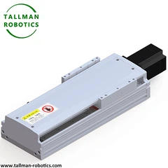


What is Cam Driven Positioning Indexer?
A cam driven positioning indexer is a precision motion control device that uses a mechanically profiled cam to convert continuous rotary input into precise, repeatable intermittent output positioning, enabling accurate angular or linear indexing without relying on servo-controlled feedback loops. Its mechanically constrained motion profile delivers highly consistent positioning accuracy and repeatability cycle after cycle.
Structure
The unit consists of a precision-machined cam (disc, cylindrical, or globoidal type) coupled to the input shaft, an output turret or shaft fitted with cam-follower rollers or bearings that trace the cam profile, and a rigid housing supporting both shafts on high-precision bearings. As the cam rotates, its contoured profile drives the follower through a defined sequence of dwell and index phases, producing precise output positioning synchronized to the input rotation.
Selection Considerations
Key factors include number of index stations, index angle, dwell-to-motion ratio, positioning accuracy and repeatability, permissible output torque and load inertia, motion curve type for smooth acceleration/deceleration, and maximum input speed. Applications requiring tight synchronization with other machine stations should verify cycle time consistency and torque capacity under peak dynamic loads.
Applications
Cam driven positioning indexers are used in packaging machinery, assembly automation, printing and labeling equipment, rotary transfer systems, and pick-and-place stations where precise, repeatable intermittent positioning is required at consistent, high-speed cycle rates without complex servo programming.
Installation Considerations
Proper alignment between the cam input shaft and output turret is critical to maintain follower engagement accuracy and prevent premature wear. The mounting base must be rigid to minimize vibration that could compromise indexing precision. Lubrication should be verified before startup, and follower preload/backlash should be checked and adjusted per manufacturer specification during commissioning to ensure accurate, smooth positioning.
Here In this page, we introduce 230 DA Cam Indexers, you will see data sheet, production pictures,videos as follows:
Also You are welcome to watch more projects or visit our video gallery by Youtube: https://www.youtube.com/@tallmanrobotics


FAQ:
1. Is it more appropriate to choose a high speed ratio or a low speed ratio splitter under high-speed conditions?
It is advisable to choose a small speed ratio for high-speed working conditions. A low speed ratio can reduce the input shaft speed, minimize inertial impact and vibration, and improve operational stability; A high speed ratio can lead to a decrease in dynamic response at high speeds.
2. Does the size of the pitch angle (travel angle) have an impact on the smoothness of the divider's operation?
influential. The larger the indexing angle, the smoother the change in the cam curve, the lower the peak acceleration, and the smoother the operation; If the graduation angle is small, the acceleration will be large, the impact will be obvious, and the stability will decrease.
3. What is the design basis for the static angle? How to match the equipment process time?
The static angle is designed based on the required time of the process to ensure that the output shaft completes the operation (such as assembly and inspection) within the static period. The static angle corresponds to the input shaft angle, and the sum of the static angle and the dynamic angle is 360 °, which must meet the requirement that the process time is ≤ static time.
4. What is the accuracy error range of the speed ratio? Will it affect the overall positioning accuracy of the device?
The speed ratio error of precision dividers is generally ≤± 0.01 ° (output shaft position accuracy). It will affect the positioning accuracy, especially when accumulating multiple workstations; But after reasonable selection, the impact on the positioning accuracy of the whole machine is controllable.
5. How to match and calculate the motor speed and divider speed ratio when a servo motor is paired with a divider?
Motor speed n (rpm)=(division angle x speed ratio)/(360 x division time) x 60. Speed ratio refers to the ratio of input speed to output speed, ensuring that n is within the rated range of the motor while meeting the division time and process cycle.
Hot Tags: cam driven positioning indexer, China cam driven positioning indexer manufacturers, suppliers, factory, Cam Indexing Device for Conveyor Systems, Cam operated Indexing and Positioning Device, Positioning focused Cam Indexing System, Mechanical Cam Indexer, Cam Actuated Multi position Indexer, Shaft with flange Cam Positioning Indexer
