
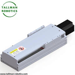


What is Motorized Cam Indexer?
A motorized cam indexer is a self-contained intermittent motion unit that integrates a precision cam mechanism with a dedicated drive motor (typically servo or geared motor) into a single assembly, delivering programmable, repeatable indexing motion without requiring a separate external drive source. This integration simplifies machine design by combining motion generation and mechanical precision indexing in one compact package.
Structure
The unit combines a servo or AC motor coupled directly (or through a reduction stage) to a cam input shaft, a precision-machined cam (disc or globoidal type) that engages an output turret via cam-follower rollers, and a rigid housing supporting both shafts on high-precision bearings. The integrated motor allows programmable control over indexing speed, dwell time, and motion profile, often coordinated with a machine's PLC or motion controller for synchronized multi-axis operation.
Selection Considerations
Key factors include number of index stations, index angle, output torque and load inertia capacity, motor power and control interface (servo vs. stepper), positioning accuracy/repeatability, motion profile flexibility, and permissible cycle rate. Applications requiring variable indexing patterns or integration with smart factory systems should prioritize units with programmable motion control capability.
Applications
Motorized cam indexers are used in packaging machinery, labeling and bottling lines, assembly automation, rotary transfer systems, and pick-and-place stations where compact, self-contained, precisely timed intermittent motion is needed, especially in space-constrained or flexible manufacturing environments.
Installation Considerations
The unit must be securely mounted on a rigid, vibration-free base to preserve indexing accuracy. Motor and cam shaft alignment should be verified during installation. Electrical connections to the motor and controller must be properly configured and tested. Lubrication levels should be checked before startup, and follower preload/backlash should be verified and adjusted per manufacturer specification during commissioning.
Here In this page, we introduce PU100DS Cam Indexers,
Also You are welcome to watch more projects or visit our video gallery by Youtube: https://www.youtube.com/@tallmanrobotics


Motorized Cam Indexer focuses on "motor-driven+cam controlled indexing":
the equipment contains customized driving motors (stepper motors or servo motors), cam components, follower units, and output systems - the motor starts after receiving control signals and drives the cam to rotate continuously through couplings (or direct connections); The cam profile is designed according to the "smooth intermittent motion law".
When the cam rotates to the "indexing section", it pushes the driven part to drive the output shaft to complete the preset angle rotation; When the cam enters the "stop section", the driven part closely adheres to the cam profile, and the output shaft stably stops until the motor drives the cam to enter the next cycle.
FAQ:
1. What speed ratio is suitable for selecting a cam indexer for multi station equipment (such as 16 stations)?
Choose a 16-stop indexer with a 16:1 speed ratio (16 input turns per output turn). This ratio gives one index per input revolution. It matches the station count and provides enough dwell time for multi-station equipment.
2. What is the difference in speed ratio selection logic between light load high-speed equipment and heavy load low-speed equipment?
Light load high-speed equipment uses a smaller speed ratio. This reduces inertia and allows faster input rotation. Heavy load low-speed equipment uses a larger speed ratio. This increases output torque and lowers impact forces.
3. How long is the customization cycle for non-standard speed ratios? Will the cost increase significantly?
Customization takes 6 to 12 weeks. Manufacturers need to redesign and grind the cam curve. Costs increase significantly, typically 30–50% higher than standard ratios.
4. What is the allowable deviation range between the actual operating speed ratio and the theoretical speed ratio of the cam indexer?
Allowable deviation stays within ±0.5% of the input angle. This limits output position error to ±0.01°–±0.02°. Larger deviation will harm positioning accuracy.
Hot Tags: motorized cam indexer, China motorized cam indexer manufacturers, suppliers, factory, Cam Indexing Device for Conveyor Systems, Cam operated Indexing and Positioning Device, Positioning focused Cam Indexing System, Mechanical Cam Indexer, Cam Actuated Multi position Indexer, Shaft with flange Cam Positioning Indexer


