


Ball Screw Linear Actuator is an electromechanical device that integrates a ball screw transmission system and a drive unit. It efficiently converts rotational motion into linear thrust or displacement by driving the ball screw with a motor, and can directly drive the load to achieve precise linear motion control. Ball Screw Linear Actuator's core characteristics are high force density, high precision, and strong controllability, making it an ideal choice to replace hydraulic/pneumatic actuators in the field of automation.
Structural composition of Ball Screw Linear Actuator, A typical structure consists of four core components:
Ball screw components: screw shaft, nut with circulating ball and pre tightening mechanism (eliminating reverse clearance);
Drive unit: Built in servo motor or stepper motor (partially including reducer), rigidly connected to the screw through a coupling;
Guidance and support: Linear bearings or guide rail sliders ensure the straightness of motion and withstand radial loads;
Shell and accessories: aluminum alloy shell (protection and heat dissipation), limit switch (travel protection), encoder (position feedback).
Working principle of Ball Screw Linear Actuator
After receiving the control signal, the motor outputs rotational torque and drives the ball screw to rotate through the coupling. The ball inside the nut rolls along the screw groove, converting the rotational motion into linear motion of the nut (when the screw is fixed) or linear motion of the screw itself (when the nut is fixed). Due to the extremely low rolling friction coefficient of the ball bearings (0.001-0.005), the transmission efficiency can reach over 90%, and the output thrust is proportional to the motor torque (thrust=torque × 2 π/lead). The speed and position of the load can be accurately controlled by controlling the motor speed and steering.
Typical applications of Ball Screw Linear Actuator
Industrial automation: material pushing device for production line (thrust 500-5000N), valve opening control (positioning accuracy ± 0.1mm);
Medical equipment: Joint drive for rehabilitation robots (with high low-speed stability requirements), bed lifting mechanism;
Smart Home: Electric Doors and Windows, Furniture Adjustment (Silent Design, Load 100-500N);
In the field of new energy: photovoltaic panel tracking system (outdoor protection level IP65), compression mechanism for battery assembly line.
Compared to hydraulic actuators, advantage of Ball Screw Linear Actuator lies in no leakage and fast response (in milliseconds); Compared to pneumatic actuators, closed-loop position control can be achieved, and thrust stability is not affected by fluctuations in gas source pressure.
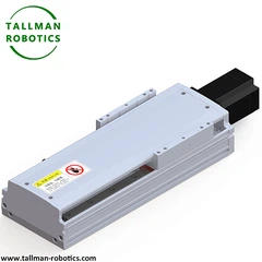
Today, here we introduce TMS45 linear moule with technical data as follows:
You are welcome to watch more projects or visit our video gallery by Youtube: https://www.youtube.com/@tallmanrobotics


Detailed description of the guiding and supporting components of ball screw linear module:
The guiding and supporting components of Ball Screw Linear Actuator are the core structures that ensure system accuracy, rigidity, and stability. Their main function is to constrain the motion trajectory (ensure linearity), withstand radial/overturning loads, and reduce motion friction. The following will explain the composition, types, key parameters, and selection principles:
1.Guiding components: the core of constraining motion trajectories
The guiding component is directly connected to the load platform to ensure that the linear motion driven by the ball screw strictly follows the preset trajectory, offsetting radial force and torque interference.
1). Core components of Ball Screw Linear Actuator
Guide rail body: a long metal component (usually made of high carbon steel or stainless steel) with high-precision tracks (such as ball grooves and roller tracks) machined on the surface as a motion reference.
Sliding block: a moving component that cooperates with a guide rail, with built-in rolling elements (balls/rollers) and a circulating structure, rigidly connected to the load platform through bolts, achieving low friction sliding.
Pre tightening mechanism: Some sliders apply pre tightening force by adjusting washers or eccentric bolts, eliminating the gap between the guide rail and the slider and improving rigidity (especially anti overturning ability).
2). Key parameters of Ball Screw Linear Actuator
Accuracy level: According to ISO standards, it is divided into C0~C9 levels. C0 level has the highest straightness (≤ 3 μ m/1000mm), while C5 level (≤ 15 μ m/1000mm) is commonly used in industry.
Rated dynamic load (C): The maximum dynamic load that the slider can withstand within its rated life (usually 50km) must be ≥ 1.2 times the actual load.
Anti overturning moment (M): The ability of the slider to resist rotation around the axis. For scenarios with large offset loads, high M value models should be selected (such as roller guides with M values more than twice that of ball guides).
2.Supporting components: stabilizing screw and overall structure
The supporting components are used to fix the two ends of the ball screw and the overall module, ensuring transmission stability and reducing vibration and deformation.
1). Core components
Screw support seat: installed at both ends of the screw, with built-in bearings (deep groove ball bearings or angular contact ball bearings) to limit the radial and axial movement of the screw.
Fixed end (one end): using an angular contact bearing group (installed face-to-face or back-to-back) to withstand axial and radial forces, ensuring the axial positioning of the screw.
Free end (other end): using deep groove ball bearings, allowing the screw to produce slight axial displacement due to thermal expansion and contraction, avoiding jamming.
Module base: The basic structure that carries guide rails, screws, and drive systems, usually made of aluminum alloy profiles (lightweight) or cast iron (high rigidity), requiring high flatness (≤ 0.1mm/m) and straightness (≤ 0.05mm/m).
Auxiliary support: For long stroke modules (>1.5m), an intermediate support seat should be added in the middle of the screw to prevent resonance (critical speed) when the screw rotates at high speed.
2). Key parameters
Bearing accuracy: P5 grade (precision grade) is usually selected for the support seat bearing to ensure that the radial runout of the screw is ≤ 0.01mm and avoid transmission eccentricity.
Base rigidity: The Young's modulus of the material determines its ability to resist deformation. Cast iron (120-160GPa) has better rigidity than aluminum alloy (60-70GPa), and is preferred for heavy-duty scenarios.
Installation benchmark: The parallelism between the guide rail installation surface on the base and the positioning surface of the screw support seat should be ≤ 0.05mm/m, otherwise it will cause additional torque during operation.
3. Collaborative design principles for guiding and supporting components
1). Load matching: In scenarios where radial load is greater than axial load, priority should be given to strengthening the guiding components (such as selecting roller guides); When axial load is the main load, focus on the axial bearing capacity of the screw support seat.
2). Precision synergy: The precision of the guide rail needs to match the precision of the ball screw (such as C3 grade screw with C3 grade guide rail) to avoid the "short board effect".
3). Environmental adaptation: Choose stainless steel guide rails and sealed sliders (protection level IP65) for humid environments; Ceramic rolling elements and high-temperature lubricating grease are required for high temperature environments (>80 ℃).
4). Installation consistency: The parallelism error between the guide rail and the screw should be ≤ 0.1mm/m, calibrated with a dial gauge, otherwise it will exacerbate wear and accuracy degradation.
The guiding components determine the linearity and load capacity of the motion trajectory, while the supporting components of Ball Screw Linear Actuator ensure the stability of the screw transmission. Both factors jointly affect the accuracy, rigidity, and lifespan of the module. When selecting, it is necessary to make a comprehensive judgment based on the load type (radial/axial), accuracy requirements, and environmental conditions. For example, semiconductor equipment should prioritize ensuring high precision of guiding components (C3 level ball guides) and low runout of support seats; Heavy machine tools need to strengthen the load-bearing capacity of guiding components (roller guides) and the rigidity of the base (cast iron material).
Hot Tags: ball screw linear actuators, China ball screw linear actuators manufacturers, suppliers, factory, High dynamic Linear System, Linear Actuator, Linear Indexing Table, Linear Sliding Table, Linear Translation Stage, Repeatable Positioning


