


What is Gear Rack and Pinion?
A gear rack and pinion is a fundamental mechanical transmission pair consisting of a straight, flat toothed bar (the rack) and a mating cylindrical gear (the pinion), used to convert rotary motion into linear motion or, conversely, linear motion into rotary motion. It is one of the simplest and most reliable methods for achieving precise linear positioning driven by a rotating motor shaft.
Structure
The rack consists of a straight bar with evenly spaced teeth machined along its length, in either straight-cut (spur) or helical tooth profiles, typically manufactured from hardened alloy steel for wear resistance. The pinion is a small cylindrical gear with matching module and pressure angle, mounted on a motor or gearbox output shaft, engaging the rack teeth to transmit force. Helical rack-and-pinion pairs offer smoother, quieter engagement than straight-cut versions due to gradual tooth contact.
Selection Considerations
Key factors include module (tooth size, which must match between rack and pinion), pressure angle, tooth profile (straight vs. helical), material hardness and surface treatment, rack length, backlash class, and required thrust force/load capacity. The pinion's reduction ratio (often via an integrated gearbox) should be selected to balance speed and torque for the target linear velocity and load.
Applications
Gear rack and pinion systems are used in CNC machine axes, gantry and Cartesian robots, elevators and lifts, steering systems, automated doors, and material handling equipment where converting rotary drive torque into precise, high-force linear motion is required.
Installation Considerations
The rack must be mounted on a flat, rigid, and accurately aligned surface parallel to the guide rail or linear bearing system. Pinion mesh depth and backlash should be set per manufacturer specification to avoid binding or excessive play. Proper lubrication should be applied to the rack teeth, and full-travel motion should be tested for smooth engagement before commissioning.
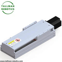
Here, in this page, we introduce model TMG135CM, and TMG135CR with technical parameter as follows:
You are welcome to watch more projects or visit our video gallery by Youtube: https://www.youtube.com/@tallmanrobotics
|
Model No |
TMG135CM |
TMG135CR |
||||
|
Motor Power (W) |
400 |
|||||
|
Repeatability (mm) |
±0.01/±0.02 |
|||||
|
Gear Teeth |
22 |
|||||
|
Gear Pitch |
5 |
|||||
|
Reduction Ratio |
1:5 |
|||||
|
Lead (mm) |
22 |
|||||
|
Max Speed(mm/s) |
1100 |
|||||
|
Motor Speed 3000(rpm/min) |
||||||
|
Max Load |
Acceleration Deceleration |
Horizontal |
0.3G |
25 |
||
|
Vertical |
0.3G |
5 |
||||
|
Rated Thrust |
56 |
|||||
|
Linear guide (mm) |
15*12.5-2 |
|||||
|
Origin Sensor |
Out plug |
EE-SX672(NPN-SX672P(PNP) |
||||
|
Inside |
E2S-W13 |
|||||
|
Closed type |
Open |
Fully-closed |
||||


Hot Tags: gear rack and pinion, China gear rack and pinion manufacturers, suppliers, factory, Linear Rack and Pinion Transmission


