
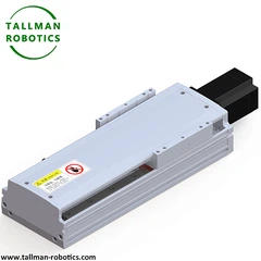


What is Linear Rack and Pinion Drive?
Linear Rack and Pinion Drive is an Industrial Long-Travel Linear Transmission System
Linear rack and pinion drive is a pure mechanical transmission system for industrial linear motion control. It engages rotary pinion gears with fixed linear racks to generate straight-line displacement. Unlike belt-driven systems, it delivers rigid mechanical transmission for stable thrust output. Moreover, it supports unlimited segmented travel extension for large industrial layouts. It serves as a core transmission solution for heavy long-travel automation equipment.
Integrated Drive Structure
First, this drive system adopts precision toothed rack bars as fixed transmission bases. It pairs hardened pinion gears to achieve tight tooth engagement. Meanwhile, parallel linear guide rails stabilize moving component trajectories.
In addition, it equips adaptive gear adjustment seats to calibrate meshing clearance. Furthermore, it installs integrated load carriages to carry operational accessories. Lastly, it adds protective covers to shield core transmission parts.
Compared to other linear transmission technologies
|
Characteristics |
Rack and Pinion Drive |
Ball Screw |
Synchronous Belt |
Linear Motor |
|
Maximum travel |
Unlimited |
≤ 6 meters |
≤ 20 meters |
≤ 10 meters |
|
Maximum speed |
10 m/s |
2 m/s |
5 m/s |
20 m/s |
|
Positioning accuracy |
± 0.02~0.5 mm |
± 0.005~0.05 mm |
± 0.1~1 mm |
± 0.001~0.01 mm |
|
Load capacity |
Ultra high (ton level) |
high (≤ 5 tons), |
medium (≤ 200kg), |
low (≤ 100kg) |
|
Maintenance costs |
Low |
medium |
Low |
high |
Here, in this page, we introduce model TMG170CM, and TMG170CR with technical parameter as follows:
You are welcome to watch more projects or visit our video gallery by Youtube: https://www.youtube.com/@tallmanrobotics
|
Model No |
TMG170CM |
TMG170CR |
|||
|
Motor Power (W) |
750 |
||||
|
Repeatability (mm) |
±0.01/±0.02 |
||||
|
Gear Teeth |
32 |
||||
|
Gear Pitch |
5 |
||||
|
Reduction Ratio |
1:5 |
1:10 |
|||
|
Lead (mm) |
32 |
16 |
|||
|
Max Speed(mm/s) |
1600 |
800 |
|||
|
Motor Speed 3000(rpm/min) |
|||||
|
Max Load |
Acceleration Deceleration |
Horizontal |
0.3G |
30 |
90 |
|
Vertical |
0.3G |
5 |
15 |
||
|
Rated Thrust |
98 |
490 |
|||
|
Linear guide (mm) |
15*12.5-2 |
||||
|
Origin Sensor |
Out plug |
EE-SX672(NPN-SX672P(PNP) |
|||
|
Inside |
EE-SX674(NPN-SX674P(PNP) |
||||
|
Closed type |
Open |
Fully-closed |
|||


Technical Features & Functional Advantages
|
Item |
Technical Feature |
Core Function |
Application Advantage |
|---|---|---|---|
|
Transmission Nature |
Hardened gear rack meshing drive |
Convert rotary power to linear thrust steadily |
Provide high-rigidity power output for heavy loads |
|
Travel Design |
Segmented splicable rack structure |
Extend linear travel without distance limit |
Fit ultra-long cross-station automation layouts |
|
Motion Performance |
Bidirectional continuous linear movement |
Support cyclic reciprocating industrial motion |
Adapt long-duration continuous operational states |
|
Structural Adaptation |
Decentralized fixed rack layout |
Match diverse gantry and linear machines |
Simplify large automation system integration |
Frequently Asked Questions
Q1: What differentiates linear rack and pinion drive from belt drive systems?
It uses rigid gear meshing transmission instead of flexible belt traction. It delivers stronger structural rigidity and heavier load capacity. It supports unlimited splicable travel, while belt drives have fixed stroke limits and weaker thrust output.
Q2: How does the system ensure stable meshing during long-travel operation?
It adopts hardened precision tooth machining to reduce meshing wear. The adjustable gear seat calibrates tooth clearance in real time. Parallel guide rails eliminate lateral deviation to keep consistent transmission accuracy.
Q3: What industrial scenarios suit linear rack and pinion drive?
It suits CNC gantry machining, large logistics gantry transfer, heavy mechanical assembly, cross-station industrial handling and all long-travel, heavy-load linear transmission automation scenarios.
Q4: Can the drive system adapt customized travel lengths?
Yes. The segmented rack structure supports free splicing and extension. It matches various on-site travel demands. The overall transmission performance remains stable after standardized assembly and calibration.
Q5: What are the inherent limitations of this linear drive?
Gear meshing produces minor mechanical backlash. It cannot reach micro-level precision of ball screw drives. It does not apply to ultra-precision micro-positioning and fine adjustment automation scenarios.
Hot Tags: linear rack and pinion drive, China linear rack and pinion drive manufacturers, suppliers, factory, Linear Rack and Pinion Transmission


