
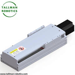


Modular Rack and Pinion System is a reconfigurable motion solution based on standardized modular design in the field of mechanical transmission. By combining gear rack components with modular architecture, Modular Rack and Pinion System achieves efficient conversion between rotational motion and linear motion. The system is designed with the core concept of "standardized unit+flexible combination", breaking the fixed structural limitations of traditional transmission systems and providing highly adaptable and cost-effective transmission solutions for fields such as industrial automation and precision machinery.
Modular Rack and Pinion System consists of three core modules:
|
Standardized rack unit |
Using high-strength alloy steel (such as 42CrMo) or stainless steel material, the surface is quenched and hardened (HRC50-60) and precision ground, with a tooth surface roughness Ra ≤ 1.6 μ m. The length of a single rack is usually 500-3000mm, with a modulus range of m=1 to m=20, and supports multiple splices to achieve infinite travel. Modular design allows users to choose between high-precision (positioning error ≤ 0.02mm/m) or heavy-duty (single load capacity ≥ 2 tons) gear racks according to their needs. |
|
Configurable gear module |
The gear adopts an involute tooth profile (pressure angle of 20 °) and forms a standard mesh with the rack. The module integrates servo motors, reducers, and encoders, supporting direct drive or deceleration transmission modes. The dual gear backlash module uses spring pre tensioning or hydraulic servo technology to control the tooth side clearance within 5 μ m, meeting the requirements of precision positioning. |
|
Intelligent Drive and Control Module |
Equipped with a fully closed-loop servo system, it supports industrial bus protocols such as EtherCAT and Modbus, and can collect real-time feedback on rack displacement (such as grating ruler signals), achieving three closed-loop control of position, speed, and torque. The modular controller supports plug and play, compatible with multi axis linkage programming and offline simulation. |
You are welcome to watch more projects or visit our video gallery by Youtube: https://www.youtube.com/@tallmanrobotics
Here, in this page, we introduce model TMG135CM, and TMG135CR with technical parameter as follows:
|
Model No |
TMG170CM |
TMG170CR |
|||
|
Motor Power (W) |
750 |
||||
|
Repeatability (mm) |
±0.01/±0.02 |
||||
|
Gear Teeth |
32 |
||||
|
Gear Pitch |
5 |
||||
|
Reduction Ratio |
1:5 |
1:10 |
|||
|
Lead (mm) |
32 |
16 |
|||
|
Max Speed(mm/s) |
1600 |
800 |
|||
|
Motor Speed 3000(rpm/min) |
|||||
|
Max Load |
Acceleration Deceleration |
Horizontal |
0.3G |
30 |
90 |
|
Vertical |
0.3G |
5 |
15 |
||
|
Rated Thrust |
98 |
490 |
|||
|
Linear guide (mm) |
15*12.5-2 |
||||
|
Origin Sensor |
Out plug |
EE-SX672(NPN-SX672P(PNP) |
|||
|
Inside |
EE-SX674(NPN-SX674P(PNP) |
||||
|
Closed type |
Open |
Fully-closed |
|||


FAQ:
1. How to choose the pre tightening method of the screw according to the positioning accuracy requirements of the linear module?
For high positioning accuracy (micron level), use double-nut preloading or oversized ball preloading. For medium accuracy, use spring preloading or light preload. For standard automation, choose no preload or minimum preload. Higher preload eliminates backlash but increases friction and heat. Match preload to your accuracy need. Do not over-preload for low-precision applications.
2. Can different brands of screws be compatible with the same model of linear module? What should be noted when selecting?
Compatibility is not guaranteed. Different brands use varying nut dimensions, lead tolerances, and end machining specs. When selecting, check the screw diameter, lead, mounting flange size, and end support bearing type. Also verify the ball circulation method and lubrication port location. Consult both manufacturers or provide detailed drawings. Mismatched screws may cause binding or premature wear.
3. How to select and solve the deflection problem of the screw rod for the ultra long stroke linear module?
Select a larger screw diameter (e.g., 25mm or 32mm for 1500mm stroke). Increase the support method to Fixed-Fixed (FK-FK) for highest rigidity. Add intermediate supports or use a rotating nut design. You can also choose a linear motor module instead of a screw. Calculate the critical speed and buckling load. Deflection degrades accuracy and causes vibration.
4. How to select the synchronous belt model for the linear module?
Calculate the required torque and belt speed. Choose belt pitch (e.g., 3M, 5M, 8M, 14M) based on load and speed. Use wider belts for higher loads. Select belt material with steel or Kevlar tension cords for low elongation. Check the pulley tooth profile and belt length. Match the belt width to the pulley flange. Refer to manufacturer's load-rating charts. Do not oversize unnecessarily.
5. What is the impact of the material of the synchronous belt (rubber/polyurethane) on the linear module and how to select it?
Rubber belts offer good flexibility and low cost but degrade with oil or ozone. Polyurethane belts provide better wear resistance, higher strength, and oil/chemical resistance. Polyurethane suits clean environments and high-speed applications. Rubber suits general automation with dust or moisture. For food or medical use, choose polyurethane with FDA approval. Match material to environmental conditions.
Hot Tags: modular rack and pinion system, China modular rack and pinion system manufacturers, suppliers, factory, Linear Rack and Pinion Transmission, rack and pinion linear modules


