
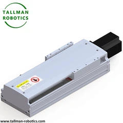


What is Rotary Indexer?
A rotary indexer is a precision motion device that converts continuous or intermittent rotary input into accurately positioned, repeatable angular output steps, enabling workpieces or tooling to be sequentially positioned at defined stations for machining, assembly, or inspection operations. Rotary indexers may be cam-driven, servo-driven, or Geneva-mechanism based, depending on the required speed, precision, and motion profile.
Structure
The device typically consists of a drive mechanism (cam, servo motor with gearbox, or Geneva wheel) coupled to an output turret or table, supported by precision bearings-often cross-roller or four-point contact type-to handle radial, axial, and moment loads. A locking or braking mechanism is frequently integrated to hold the output position rigidly during dwell periods, ensuring stability during machining or assembly operations performed at each station.
Selection Considerations
Key factors include number of index stations, index angle, positioning accuracy and repeatability, permissible load capacity and moment loading, dwell time and cycle rate, locking/braking torque, and drive type (mechanical cam vs. servo-driven for flexible station counts). Applications requiring variable indexing patterns should favor servo-driven units, while high-speed fixed-station applications often benefit from cam-driven designs for mechanical reliability.
Applications
Rotary indexers are used in assembly automation, machining transfer lines, packaging and labeling equipment, welding and inspection stations, and pick-and-place systems where workpieces must be precisely and repeatedly positioned at multiple stations during a production cycle.
Installation Considerations
The indexer must be mounted on a rigid, vibration-free base with verified alignment to upstream and downstream equipment. Locking/braking mechanisms should be tested under load to confirm holding torque. Lubrication should be checked before startup, and positioning accuracy, repeatability, and backlash should be verified during commissioning to ensure consistent station-to-station performance.
Here In this page, we introduce series of Rotary Indexer,
you will see data sheet, production pictures,videos of test as follows:
Also You are welcome to watch more projects or visit our video gallery by Youtube: https://www.youtube.com/@tallmanrobotics
|
Specification |
TMDL-60 |
TMDL-85 |
TMDL-130 |
TMDL-200 |
TMDL280 |
|
|
Reduction ratio |
30/60/90 |
10.25/30/60/90 |
10.25/30/60/90 |
10.25/30/60/90 |
30/60/90 |
|
|
Admissible thrust load (Kgs) |
50 |
60 |
160 |
250 |
480 |
|
|
Bearings |
High rigidity, high load, output integrated cross roller bearing |
|||||
|
Lifespan (Hours) |
20000 |
|||||
|
positioning accuracy (arc-min) |
≤1′ |
≤1′ |
≤1′ |
≤1′ |
≤1′ |
|
|
Rotation platform plane jumping (mm) |
≤0.01 |
≤0.01 |
≤0.01 |
≤0.01 |
≤0.01 |
|
|
Rotation platform radial runout (mm) |
≤0.01 |
≤0.01 |
≤0.01 |
≤0.01 |
≤0.01 |
|
|
Protection class(IP) |
IP40 |
IP40 |
IP40 |
IP40 |
IP40 |
|
|
Weight(kgs) |
1.0kgs |
2.5kgs |
5.5kgs |
15kgs |
45kgs |
|
|
Servo motor/Stepper |
42 Servo motor/42 stepper |
60 Servo motor/57 stepper |
60 Servo motor/57 stepper |
80 Servo motor/86 stepper |
130 Servo motor |
|


FAQ:
1. How to choose a suitable hollow rotating platform based on the load weight?
First calculate the total load weight including fixtures and workpieces. Distinguish three load types: axial load (vertical force), radial load (horizontal force), and overturning moment (eccentric force). Calculate the overturning moment by multiplying load weight by eccentric distance[reference:0]. Then compute required torque using total inertia and acceleration. Select a platform whose rated output torque exceeds the total demand by a safety factor of 1.5 to 2.0. Check manufacturer's load rating charts.
2. What is the load holding capacity of the hollow rotating platform?
The load holding capacity refers to the static holding torque or braking torque. It maintains the platform's position when the motor de-energizes. The motor's electromagnetic brake provides this function. For critical applications, manufacturers offer mechanical brakes that directly lock the output flange for greater safety and holding force. When selecting, verify that the holding torque meets or exceeds the system's requirements.
3. What is the difference in selection criteria between dynamic and static loads?
Static load applies when the platform remains stationary. It equals the weight of the platform plus the supported object Dynamic load occurs during rotation or acceleration. It creates inertial forces and shock loads. Always consider both when selecting a platform. Static load determines the basic capacity. Dynamic load, combined with speed and acceleration, determines the required torque and bearing life. Dynamic loads often exceed static loads due to acceleration forces.
4. Which type of transmission is recommended for a rotating platform under high load conditions?
For high load conditions, choose a planetary gear system or a heavy-duty worm gear. Planetary gears provide high torque density, rigidity, and efficiency[reference:9]. Heavy loads may require additional planetary reducers to increase output torque. Some high-capacity platforms use 30:1 reduction ratios with axial load capacities up to 200 kg. Integrated motor-platform units with cross-roller bearings also deliver high output torque and handle heavy loads effectively.
5. What are the load testing standards for hollow rotating platforms?
Standards include GB/T 228.1-2021 for static load testing (150% of maximum working load, permanent deformation ≤0.2%). Fatigue life assessment requires ≥10⁶ cycles. Torque testing at 120% of rated torque with efficiency loss ≤3%. Manufacturers also test bearing wear (maximum 0.3 mm) and temperature rise (≤40°C). ISO 14122-3 and GB/T 3811 apply for structural safety. Always request test reports from your supplier.
Hot Tags: rotary indexer, China rotary indexer manufacturers, suppliers, factory, Through Hole Rotary Tables, Hypoid Gear Equipped Hollow Actuator, Large Aperture Rotary Tables, Pulsed Cam Indexing Device, Heavy Duty Hollow Rotary Work Platform, Electric Motor Driven Rotary Table


