
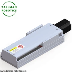


What is Multi-Axis Cartesian Robot?
A multi-axis Cartesian robot is an automated positioning system that combines multiple linear axes-typically X, Y, Z, and sometimes additional linear or rotary axes-arranged along mutually perpendicular directions to achieve precise, programmable motion within a defined rectangular work volume. Extending beyond the basic 3-axis configuration, "multi-axis" often indicates additional linear travel axes or supplementary rotary axes (e.g., a 4th axis for tool rotation) integrated into the same coordinated Cartesian framework.
Structure
The robot consists of a base frame supporting the primary X-axis rails, a carriage traversing the X-axis carrying the Y-axis assembly, a Z-axis for vertical motion, and optionally additional linear axes or a rotary axis mounted at the tool point for part orientation. Each axis is independently driven by ball screw, belt-drive, or linear motor mechanisms paired with servo motors, guided by linear rails, with encoders on every axis feeding a central multi-axis motion controller for fully coordinated, synchronized movement.
Selection Considerations
Key factors include number and configuration of axes, travel range per axis, payload capacity, positioning accuracy and repeatability, maximum speed/acceleration, drive type matched to each axis's precision/speed needs, additional rotary axis torque and orientation range (if included), and controller capability for coordinated multi-axis path interpolation.
Applications
Multi-axis Cartesian robots are used in complex assembly, dispensing with part orientation, CNC machining support, 3D printing with rotational features, precision inspection, and material handling tasks requiring both linear positioning and additional orientation control beyond simple 3-axis motion.
Installation Considerations
The base frame must be installed level, square, and rigidly anchored to support combined multi-axis loads without deflection. Perpendicularity across all linear axes and calibration of any rotary axis should be verified during commissioning. Cable management must accommodate simultaneous multi-axis travel, and full-envelope, full-rotation motion accuracy should be tested before production use.
You are welcome to watch more projects or visit our video gallery by Youtube: https://www.youtube.com/@tallmanrobotics
|
|
|
|
|
|
TM-FA |
TM-FB |
TM-FB2Z2 |
TM-FBZ2 |
|
|
|
|
|
|
TM-FC |
TM-FCZ |
TM-FD |
TM-FDZ |
|
|
|
|
|
|
TM-FE |
TM-FEZ |
TM-FF |
TM-FFZ |
|
|
|
|
|
|
TM-FG |
TM-FF2 |
TM-FGZ |
TM-FBZ2 |


|
Model of Each Axis |
Model of Each Axis |
Model of Each Axis |
||||||
|
X Axis |
Y Axis |
Z Axis |
X Axis |
Y Axis |
Z Axis |
X Axis |
Y Axis |
Z Axis |
|
TM100 |
TM45 |
TM135 |
TM100 |
TM100 |
TM150 |
TM135 |
TM135 |
|
|
TM100 |
TM62 |
TM135 |
TM135 |
TM100 |
TM200 |
TM100 |
TM62 |
|
|
TM100 |
TM100 |
TM45 |
TM135 |
TM135 |
TM135 |
TM200 |
TM100 |
TM100 |
|
TM100 |
TM100 |
TM62 |
TM150 |
TM62 |
TM200 |
TM135 |
TM100 |
|
|
TM100 |
TM100 |
TM100 |
TM150 |
TM100 |
TM62 |
TM200 |
TM150 |
TM100 |
|
TM135 |
TM62 |
TM150 |
TM100 |
TM100 |
TM200 |
TM150 |
TM135 |
|
|
TM135 |
TM100 |
TM62 |
TM150 |
TM135 |
TM100 |
|||
|
Model of Each Axis |
Model of Each Axis |
Model of Each Axis |
|||||||
|
X Axis |
Y Axis |
Z Axis |
X Axis |
Y Axis |
Z Axis |
X Axis |
Y Axis |
Z Axis |
|
|
TM100 |
TM45 |
TM135 |
TM100 |
TM100 |
TM150 |
TM135 |
TM135 |
||
|
TM100 |
TM62 |
TM135 |
TM135 |
TM100 |
TM200 |
TM100 |
TM62 |
||
|
TM100 |
TM100 |
TM45 |
TM135 |
TM135 |
TM135 |
TM200 |
TM100 |
TM100 |
|
|
TM100 |
TM100 |
TM62 |
TM150 |
TM62 |
TM200 |
TM135 |
TM100 |
||
|
TM100 |
TM100 |
TM100 |
TM150 |
TM100 |
TM62 |
TM200 |
TM150 |
TM100 |
|
|
TM135 |
TM62 |
TM150 |
TM100 |
TM100 |
TM200 |
TM150 |
TM135 |
||


FAQ
How is a multi-axis Cartesian robot different from a standard 3-axis Cartesian robot?
A multi-axis Cartesian robot includes additional linear or rotary axes beyond the standard X, Y, Z, enabling more complex motion such as part rotation or extended travel not possible with a basic 3-axis setup.
Can a multi-axis Cartesian robot include rotary motion?
Yes, many configurations add a rotary axis, often at the Z-axis tool point, to allow part or tool orientation while retaining the core linear Cartesian structure for primary positioning.
What industries commonly use multi-axis Cartesian robots?
They are widely used in electronics assembly, automotive component handling, packaging, 3D printing, and precision dispensing applications requiring both linear positioning and supplementary axis control.
How does adding axes affect programming complexity?
Additional axes require more sophisticated motion controllers capable of coordinated multi-axis interpolation, increasing programming complexity compared to simpler 3-axis point-to-point motion.
What's the typical payload capacity of a multi-axis Cartesian robot?
Payload capacity varies significantly by frame size and drive type, ranging from a few kilograms for compact benchtop units to hundreds of kilograms for industrial-scale multi-axis gantry systems.
Hot Tags: multi axis cartesian robot, China multi axis cartesian robot manufacturers, suppliers, factory, Multi Axis Linear Motion Stage, Multi Axis Linear Platform System, 3 Axis Gantry Platform, Multi Axis Linear Positioning System, Multi Axis Linear Actuator Module, Triaxial Gantry Manipulator


