
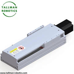


Telescopic Linear Actuator: Technical Overview for Industrial Automation
What Is a Telescopic Linear Actuator
A telescopic linear actuator converts rotary or linear input into extended reach through nested, sliding tube sections. Each section retracts inside the next, similar to a collapsible antenna. This design multiplies stroke length far beyond the actuator's retracted footprint. Engineers value this feature for applications where compact storage space limits standard single-stage actuators. Consequently, the telescopic linear actuator serves tasks that require long travel distances alongside tight installation clearances.
Manufacturers typically build the actuator around two to four telescoping stages. Each stage carries its own drive mechanism, guide rail, or synchronized cable system. As a result, the actuator tube extends in a coordinated sequence rather than a single uniform motion. The extension ratio, meaning the relationship between retracted length and full stroke length, defines the actuator's usable travel. A higher extension ratio delivers greater reach from a smaller housing. Therefore, engineers select the telescopic linear actuator specifically for lifting platforms, access ramps, and adjustable support columns.
You are welcome to watch more projects or visit our video gallery by Youtube: https://www.youtube.com/@tallmanrobotics
Here, we introduce Telescopic Linear Actuator by Fully Sealed Screw drive linear Modules for Clean Environment from Tallman Robot with following series TMS-CR.


Structural Design and Core Components
The telescopic linear actuator combines several core components into one coordinated linear motion system. First, the outer tube anchors the actuator to its mounting base and houses the drive motor. Next, one or more intermediate tubes nest inside the outer tube and carry synchronization hardware. Finally, the inner tube, or ram, delivers the working stroke and connects to the load.
A synchronization mechanism coordinates the extension sequence across all stages. Designers commonly use a cable-and-pulley system, a rack-and-pinion linkage, or a nested screw arrangement for this purpose. Each method keeps the stages moving at a proportional rate, so the outer stage extends first and the inner stage follows in sequence. This sequencing prevents binding and maintains consistent load capacity throughout the full stroke length.
The drive mechanism sits at the actuator's base and generates the primary motion. Common drive options include an electric motor paired with a lead screw, a ball screw assembly for higher precision, or a hydraulic cylinder for heavy load capacity. Additionally, guide bushings or roller bearings support each tube section and reduce friction during extension and retraction. Sealing components, including wiper rings and dust boots, protect internal surfaces from contamination. In turn, this protection extends actuator service life in demanding industrial automation environments.
Application Areas Across Industrial Automation
The telescopic linear actuator supports a wide range of industrial automation tasks that require long stroke length within a compact envelope. For example, material handling systems use the actuator to raise and lower conveyor sections during changeovers. Similarly, packaging lines rely on the actuator for height-adjustable infeed stations that accommodate multiple container sizes.
Robotic work cells also incorporate the telescopic linear actuator for auxiliary lift functions. Specifically, a robot arm platform may ride on the actuator to reach raised or lowered work zones without repositioning the entire cell. Furthermore, medical device assembly stations use compact telescopic units to adjust fixture height between shifts. Solar panel tracking systems apply the same principle at a larger scale, extending support arms to follow the sun's angle throughout the day.
Automotive assembly lines benefit from the actuator's high load capacity during body panel positioning tasks. Meanwhile, warehouse automation systems use telescopic actuators inside automated storage and retrieval units to extend picking arms into deep rack positions. Across these examples, the telescopic linear actuator consistently delivers long reach, stable support, and repeatable positioning accuracy. Palletizing cells also apply the actuator to raise stacking arms above growing product columns, and this application benefits directly from the actuator's compact retracted footprint. Similarly, inspection stations use telescopic units to lower cameras or sensors close to a moving line, then retract fully out of the workspace between cycles. Each use case shares one common requirement: a linear motion system that delivers long stroke length without occupying excessive fixed space.
Installation Guidelines for Telescopic Linear Actuators
Correct installation determines the actuator's long-term positioning accuracy and load capacity. First, technicians confirm the mounting surface meets the flatness tolerance specified by the actuator manufacturer. An uneven surface introduces side-loading that accelerates wear on guide bushings and seals. Next, installers align the actuator's centerline with the intended direction of travel. Misalignment creates binding between telescoping stages and reduces the effective stroke length.
Technicians then secure the base mounting bracket using the specified bolt pattern and torque values. Afterward, they connect the drive mechanism to its power source, whether electric, pneumatic, or hydraulic. Wiring routes should include adequate slack to accommodate full extension without strain. Consequently, cable management systems, such as drag chains, commonly pair with the telescopic linear actuator in industrial automation cells.
Once installers complete mechanical and electrical connections, they perform a controlled test cycle. This cycle should extend the actuator through its full stroke length at reduced speed. Operators observe each stage for smooth transitions and listen for unusual noise. Finally, technicians verify limit switch settings and confirm the actuator stops precisely at both fully retracted and fully extended positions. Regular lubrication of guide surfaces further supports consistent performance and protects rated load capacity over time.
Selection Considerations for Engineers
Engineers evaluate several variables, then specify a telescopic linear actuator for a new industrial automation project. Load capacity ranks as a primary factor. The actuator must support the intended payload throughout the entire stroke length, not only at full extension. Side loading also matters. A telescopic linear actuator handles axial loads efficiently, but excessive lateral force accelerates wear on guide bushings and shortens service life. Consequently, engineers often add external guide rails or support brackets for applications with significant side loading.
Stroke length and extension ratio work together to define the actuator's footprint. A project with limited retracted clearance benefits from a higher extension ratio, achieved through additional telescoping stages. However, additional stages introduce more moving joints, which can reduce overall stiffness. Therefore, engineers balance compactness against rigidity based on the specific application.
Environmental conditions also shape actuator selection. Washdown environments in food and beverage processing call for sealed guide bushings and corrosion-resistant materials. Similarly, dusty environments in material handling or automotive plants benefit from dust boots and wiper seals that protect internal surfaces. Duty cycle represents another key consideration. Continuous-motion applications, such as automated storage and retrieval systems, require actuators rated for frequent cycling. Occasional-use applications, such as adjustable support columns, tolerate lighter duty ratings by comparison.
Finally, control integration influences the drive mechanism choice. Applications that require synchronized motion with a robot arm or conveyor system typically pair the telescopic linear actuator with a servo motor and closed-loop feedback. This configuration allows a programmable logic controller to coordinate the actuator's position with other automated equipment in real time. In contrast, simpler applications may use an open-loop electric or pneumatic drive mechanism without position feedback.
Technical Reference Table
The table below summarizes typical performance characteristics across common telescopic linear actuator configurations used in industrial automation.
|
Stage Count |
Extension Ratio |
Drive Mechanism |
Typical Load Capacity |
Typical Stroke Length |
|
2-Stage |
Up to 2.5:1 |
Lead screw / electric motor |
Light to medium duty |
200-600 mm |
|
3-Stage |
Up to 3.8:1 |
Ball screw / servo motor |
Medium duty |
400-1200 mm |
|
4-Stage |
Up to 5:1 |
Cable-synchronized / servo motor |
Medium to heavy duty |
800-2000 mm |
|
Hydraulic Multi-Stage |
Up to 4:1 |
Hydraulic cylinder |
Heavy duty |
500-3000 mm |
This comparison highlights a clear pattern. Higher stage counts increase the extension ratio and overall stroke length through multi-stage extension. Drive mechanism selection independently governs precision and load capacity. Engineers match these variables to the specific industrial automation task, then finalize the selection.
Frequently Asked Questions
1. What distinguishes a telescopic linear actuator from a standard single-stage actuator?
A telescopic linear actuator uses multiple nested tube sections to achieve a longer stroke length relative to its retracted size. A standard single-stage actuator extends only as far as its single tube allows, so it requires a longer retracted footprint for equal travel.
2. How does the extension ratio affect actuator selection?
The extension ratio compares the retracted length to the full stroke length. A higher ratio allows engineers to specify a shorter, more compact actuator for a given travel requirement, which supports installations with restricted mounting space.
3. Which drive mechanism suits high-precision industrial automation tasks?
Ball screw and servo motor combinations generally suit tasks that require precise, repeatable positioning. Hydraulic cylinders suit tasks that prioritize heavy load capacity over positioning precision.
4. What maintenance practices extend actuator service life?
Regular lubrication of guide surfaces, periodic inspection of seals and wiper rings, and prompt correction of mounting misalignment all support long-term actuator performance and protect rated load capacity.
5. Can a telescopic linear actuator operate in washdown or dusty environments?
Yes, provided the unit includes sealed guide bushings, dust boots, and corrosion-resistant materials suited to the environment. Engineers should confirm the ingress protection rating against the specific industrial automation application, then proceed with installation.
Hot Tags: telescopic linear actuator, China telescopic linear actuator manufacturers, suppliers, factory, Precision Positioning, Cross Roller Stage, Linear Feed Platform, Miniature Linear Actuator, Ball Screw Driven Linear Stage, Linear Material Transfer Unit


