


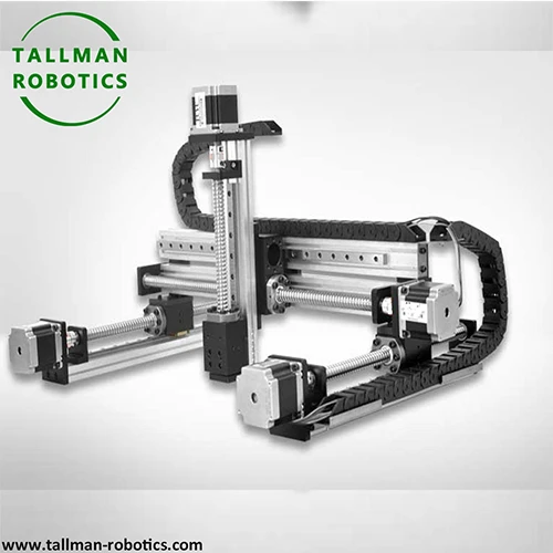


3 Axis Gantry System, also known as gantry type Cartesian coordinate robot, is a crucial large-scale high-end equipment in the field of industrial automation. It has become an indispensable core solution for high-end manufacturing, precision machining, and heavy-duty handling applications due to its excellent stability, large working range, extremely high rigidity, and micrometer level repetitive positioning accuracy. It can be regarded as the "steel arm" and "precision cornerstone" of modern intelligent factories.
The core feature of 3 Axis Gantry System is its unique bridge type (door type) structure. Its X-axis is usually composed of two parallel sturdy crossbeams (or "sky beams") that span the entire work area and are supported and fixed by pillars ("legs") or sturdy bases on both sides. The Y-axis crossbeam moves laterally on the X-axis, while the Z-axis carries end effectors (such as the spindle, gripper, and nozzle) to achieve vertical up and down movement. This symmetrical closed frame structure brings unparalleled mechanical rigidity and stability, effectively suppressing vibrations and deformations generated during motion, providing a solid physical foundation for ultra-high precision operations.
3 Axis Gantry System is usually co controlled by PLC or professional motion controllers, and can achieve complex trajectory movements such as straight lines and arcs through programming. Some high-end models also integrate visual recognition systems, which use industrial cameras to capture the position of workpieces in real time, achieving automatic correction and path planning. In addition, the system supports multi axis linkage and can control the end effector to complete complex actions in three-dimensional space, adapting to various industrial scenarios.
The inherent advantages of 3 Axis Gantry System enable it to easily achieve a much larger working range than other robots, covering huge working areas of several meters or even tens of meters square. At the same time, its powerful structural design also means that it has extremely high load capacity, which can drive heavy-duty spindles or transport hundreds of kilograms of workpieces. Most importantly, thanks to its excellent rigidity and precise transmission system (such as high-precision linear motors and dual servo motor driven clearance), 3 Axis Gantry System can maintain ultra high positioning accuracy and repeatability at the micrometer level (μ m) for a long time in the entire huge motion space, which is difficult to achieve with cantilever structures.
You are welcome to watch more projects or visit our video gallery by Youtube: https://www.youtube.com/@tallmanrobotics
|
|
|
|
|
|
TM-FA |
TM-FB |
TM-FB2Z2 |
TM-FBZ2 |
|
|
|
|
|
|
TM-FC |
TM-FCZ |
TM-FD |
TM-FDZ |
|
|
|
|
|
|
TM-FE |
TM-FEZ |
TM-FF |
TM-FFZ |
|
|
|
|
|
|
TM-FG |
TM-FF2 |
TM-FGZ |
TM-FBZ2 |




|
Model of Each Axis |
Model of Each Axis |
Model of Each Axis |
||||||
|
X Axis |
Y Axis |
Z Axis |
X Axis |
Y Axis |
Z Axis |
X Axis |
Y Axis |
Z Axis |
|
TM100 |
TM45 |
TM135 |
TM100 |
TM100 |
TM150 |
TM135 |
TM135 |
|
|
TM100 |
TM62 |
TM135 |
TM135 |
TM100 |
TM200 |
TM100 |
TM62 |
|
|
TM100 |
TM100 |
TM45 |
TM135 |
TM135 |
TM135 |
TM200 |
TM100 |
TM100 |
|
TM100 |
TM100 |
TM62 |
TM150 |
TM62 |
TM200 |
TM135 |
TM100 |
|
|
TM100 |
TM100 |
TM100 |
TM150 |
TM100 |
TM62 |
TM200 |
TM150 |
TM100 |
|
TM135 |
TM62 |
TM150 |
TM100 |
TM100 |
TM200 |
TM150 |
TM135 |
|
|
TM135 |
TM100 |
TM62 |
TM150 |
TM135 |
TM100 |
|||
|
Model of Each Axis |
Model of Each Axis |
Model of Each Axis |
|||||||
|
X Axis |
Y Axis |
Z Axis |
X Axis |
Y Axis |
Z Axis |
X Axis |
Y Axis |
Z Axis |
|
|
TM100 |
TM45 |
TM135 |
TM100 |
TM100 |
TM150 |
TM135 |
TM135 |
||
|
TM100 |
TM62 |
TM135 |
TM135 |
TM100 |
TM200 |
TM100 |
TM62 |
||
|
TM100 |
TM100 |
TM45 |
TM135 |
TM135 |
TM135 |
TM200 |
TM100 |
TM100 |
|
|
TM100 |
TM100 |
TM62 |
TM150 |
TM62 |
TM200 |
TM135 |
TM100 |
||
|
TM100 |
TM100 |
TM100 |
TM150 |
TM100 |
TM62 |
TM200 |
TM150 |
TM100 |
|
|
TM135 |
TM62 |
TM150 |
TM100 |
TM100 |
TM200 |
TM150 |
TM135 |
||


In practical applications, 3 Axis Gantry System is widely used. On the photovoltaic module production line, it can accurately complete the handling and serial welding of solar cells; In the field of warehousing and logistics, automated storage and palletizing of goods can be achieved; In the laser processing industry, high-precision positioning ensures the accuracy of laser cutting and engraving. Its modular design facilitates installation and maintenance, and users can flexibly expand the number of axes and work range according to their needs, combining efficiency and cost-effectiveness, making it a reliable choice for upgrading industrial automation.
Hot Tags: 3 axis gantry system, China 3 axis gantry system manufacturers, suppliers, factory, Multi Axis Linear Actuator Module, Multi Axis Linear Motion Stage, Multi Axis Linear Positioning Module, Pinion rack linear actuators, XY Axis Linear Stage


